
CNC Machining Services: Deep-Hole Machining and L/D Ratio Control
Deep-hole machining is a demanding application within CNC Machining Services because increasing hole depth changes the relationship between tool rigidity, chip evacuation, cooling, cutting force and dimensional accuracy. A deep hole is not simply a standard drilling operation performed with a longer drill. As the depth-to-diameter ratio increases, tool deflection, hole-axis deviation, oversize, burr formation and heat management become increasingly important. Proper drilling strategy, tool selection, coolant delivery and inspection are therefore essential for reliable deep-hole production.
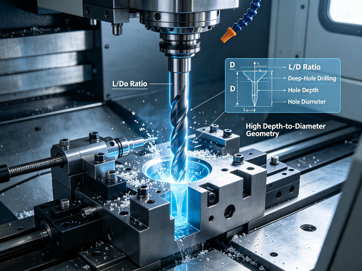
Deep-hole machining generally refers to producing holes where the hole depth is significantly greater than the hole diameter. The depth-to-diameter relationship is commonly expressed as the L/D ratio, where L represents the effective hole depth and D represents the hole diameter.
The exact threshold used to classify a hole as “deep” depends on the machining method, material, tool type and production requirements. A hole that is straightforward for one drilling system may become challenging for another.
As L/D increases, the drill becomes more sensitive to deflection and vibration. Chip evacuation also becomes more difficult because chips must travel a greater distance through or out of the hole.
| Machining condition | Increasing challenge | Primary engineering concern |
|---|---|---|
| Low L/D ratio | Relatively short drilling path | Basic hole size and surface condition |
| Moderate L/D ratio | Longer tool engagement | Tool rigidity and chip evacuation |
| High L/D ratio | Long drilling distance | Deflection, heat and axis deviation |
| Very deep hole | Limited access and difficult chip removal | Specialized drilling process and inspection |
pemVerify all parameters against current test reports and applicable standards before use in specifications.emp
The L/D ratio provides a simple way to understand why a drilling operation becomes progressively more difficult as depth increases.
Consider two holes with the same diameter but different depths. The shorter hole allows the drill to remain relatively well supported. The deeper hole requires a longer cutting engagement and provides more opportunity for the tool to deflect.
When the drill is not perfectly rigid, cutting forces can cause the tool to move away from its intended axis. This may produce a hole that is larger than expected, slightly angled, or positioned differently at the exit than at the entry.
L/D ratio should therefore be reviewed during DFM rather than only after a drilling problem occurs.
Long tool overhang
Small drill diameter
Hard or difficult-to-machine material
Interrupted cutting conditions
Poor chip evacuation
Insufficient coolant delivery
Tool wear
Unstable workholding
Deep blind-hole geometry
Strict hole position or straightness requirements
Conventional drilling is often effective for relatively shallow holes. The drill enters the material, produces chips and removes them through the flute geometry or coolant flow.
As hole depth increases, the standard drilling approach may become less effective. Chips have more distance to travel, coolant may have difficulty reaching the cutting edge, and heat can accumulate within the hole.
For deeper holes, specialized drilling methods may provide better control. Depending on the application, these can include Peck Drilling, through-tool coolant drilling, gun drilling or other deep-hole drilling techniques.
| Method | Typical characteristic | Engineering consideration |
|---|---|---|
| Conventional drilling | Simple and widely applicable | Best suited to appropriate hole depths and geometries |
| Peck drilling | Periodic tool withdrawal | Helps break and evacuate chips |
| Through-tool coolant drilling | Coolant delivered through the tool | Improves cooling and chip evacuation |
| Gun drilling | Designed for deep and relatively straight holes | Requires suitable equipment and process control |
pemVerify all parameters against current test reports and applicable standards before use in specifications.emp
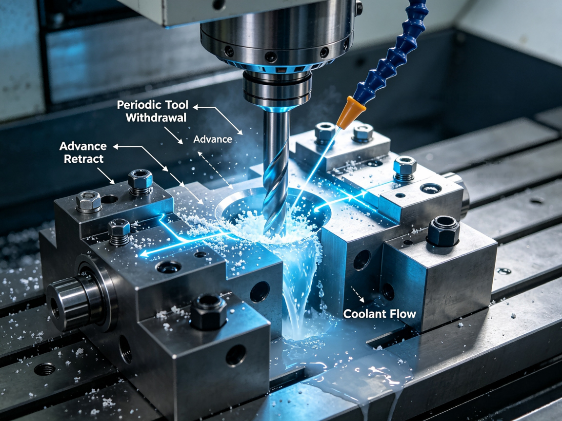
Peck drilling divides the drilling operation into repeated cutting and withdrawal cycles. Instead of continuously advancing the drill to the final depth, the tool periodically retracts to help remove accumulated chips and introduce coolant into the cutting area.
This can be useful when chip accumulation becomes a limiting factor.
However, peck drilling is not automatically the best solution for every deep hole. Excessive retract cycles can increase machining time, and poorly selected peck depths can still result in chip packing or unstable cutting.
The appropriate cycle should consider material, drill geometry, hole diameter, depth, coolant conditions and machine capability.
Initial drilling depth
Peck depth
Retract distance
Feed rate
Spindle speed
Coolant delivery
Material type
Chip formation
Hole depth
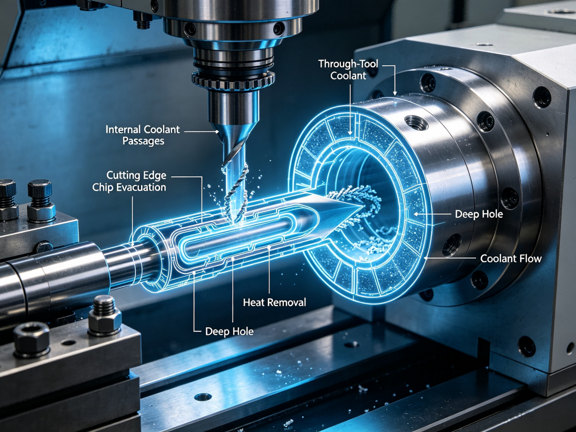
Through-tool coolant, sometimes called through-spindle coolant, delivers cutting fluid through passages in the cutting tool. For suitable drilling applications, this allows coolant to reach the cutting zone more directly than external coolant alone.
This can help with two major deep-hole challenges: heat removal and chip evacuation.
When chips accumulate near the drill point, they can be recut or packed tightly inside the hole. This can increase cutting force, damage the tool and affect hole quality.
Through-tool coolant can help move chips away from the cutting edge while carrying heat out of the hole.
| Cooling approach | Potential advantage | Deep-hole limitation |
|---|---|---|
| External coolant | Simple and widely available | Access to deep cutting zones may be limited |
| High-pressure external coolant | Improved chip movement | Effectiveness depends on tool and hole geometry |
| Through-tool coolant | Direct delivery near cutting edge | Requires compatible tooling and machine capability |
pemVerify all parameters against current test reports and applicable standards before use in specifications.emp
Tool deflection is one of the most important concerns in deep-hole machining. A slender drill behaves differently from a short, rigid cutting tool.
When cutting force acts on a long tool, even a relatively small force can create measurable displacement. If the tool begins to deviate from its intended axis, the resulting hole may gradually move away from the programmed centerline.
The problem can become more serious when the drill encounters uneven material, interrupted surfaces or changing cutting resistance.
Deep-hole straightness therefore depends on more than machine positioning accuracy. Tool rigidity, starting conditions, material homogeneity, workpiece stability and drilling method all contribute to the result.
Drill deflection
Improper tool selection
Uneven cutting forces
Tool wear
Workpiece movement
Improper entry conditions
Chip accumulation
Excessive cutting parameters
Insufficient tool guidance
The first stage of drilling can influence the accuracy of the entire hole. If the drill does not enter the workpiece accurately, subsequent cutting may follow an incorrect trajectory.
For precision deep holes, the starting surface should therefore provide a stable and properly prepared entry condition.
Depending on the component geometry, a center-drilled, spot-drilled or otherwise prepared entry can help establish a controlled starting point. The exact approach depends on the drill design and required hole accuracy.
An uneven or angled entry surface can increase the risk of drill walking or uneven cutting forces at the beginning of the operation.
Blind holes create additional challenges because the chips have fewer opportunities to exit naturally through the workpiece.
The bottom of the hole can also require specific geometry depending on whether the hole will contain a fastener, thread, dowel, spring, insert or other component.
Engineering drawings should distinguish between total hole depth and effective functional depth. A drill point, chamfer or incomplete thread section may occupy part of the nominal hole depth.
| Blind-hole characteristic | Potential issue | Engineering response |
|---|---|---|
| Limited chip exit | Chip accumulation | Use suitable chip evacuation strategy |
| Deep bottom section | Tool access limitation | Select appropriate drill geometry and cycle |
| Threaded blind hole | Insufficient effective thread depth | Define required thread depth separately |
| Critical bottom depth | Risk of over-drilling | Control programmed and verified depth |
pemVerify all parameters against current test reports and applicable standards before use in specifications.emp
Material selection has a direct influence on drilling behavior. Aluminum, carbon steel, stainless steel and other engineering materials produce different chip shapes, cutting forces and thermal conditions.
Aluminum can generate long or sticky chips under unsuitable cutting conditions, while some steels can create high cutting forces and heat. Stainless steels may present work-hardening and heat-management challenges if the cutting process is unstable.
The drilling strategy should therefore be adapted to the material rather than applying one fixed cycle to every component.
Hardness
Toughness
Thermal conductivity
Chip formation characteristics
Work-hardening tendency
Tool compatibility
Coolant requirements
Tool wear can become especially important in deep-hole production because the drill operates under restricted cutting conditions for an extended distance.
As the cutting edge wears, cutting forces may increase. Hole diameter, surface condition and dimensional consistency can gradually change.
A worn drill can also increase heat generation and make chip evacuation less stable.
For production runs, tool condition should therefore be monitored rather than relying only on a fixed number of parts before replacement.
| Tool condition | Potential effect | Inspection concern |
|---|---|---|
| New tool | Stable cutting edge | Establish baseline dimensions |
| Normal wear | Gradual cutting-force change | Monitor hole size and surface condition |
| Significant wear | Higher force and heat | Risk of dimensional drift |
| Damaged tool | Unstable cutting | Potential hole geometry failure |
pemVerify all parameters against current test reports and applicable standards before use in specifications.emp
Burrs can form at both the entrance and exit of a drilled hole. Exit burrs are particularly important when the drill breaks through the opposite surface because the remaining material becomes progressively thinner near breakthrough.
Excessive burrs can interfere with assembly, sealing, fastener installation or subsequent finishing operations.
Burr formation depends on material, tool geometry, feed conditions, cutting-edge condition and breakthrough strategy.
For precision components, deburring should be treated as part of the manufacturing process rather than an afterthought.
Deep holes are frequently followed by tapping or Thread Milling. The quality of the drilled hole directly affects the subsequent threading operation.
If the drilled hole is undersized, oversized, misaligned or contains excessive burrs, the threading process may become unstable.
For blind threaded holes, the engineer should also distinguish between drill depth, thread depth and required effective thread length.
A hole may appear sufficiently deep based on its nominal measurement while providing insufficient usable depth after accounting for the drill point and incomplete thread region.
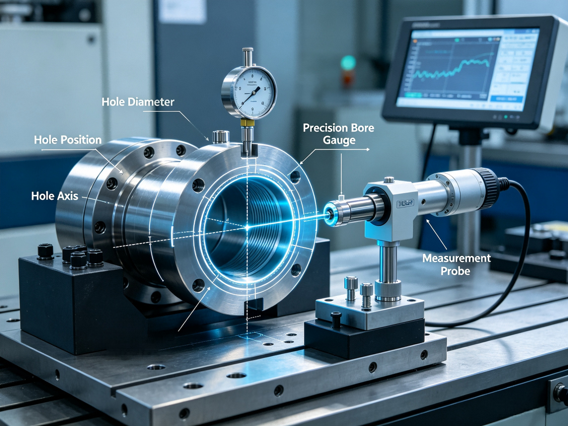
Deep-hole inspection can be more difficult than standard dimensional inspection because the critical geometry may be inaccessible from the outside.
Depending on the requirement, inspection may involve pin gauges, bore gauges, coordinate measurement systems, specialized probes or other suitable measurement equipment.
The inspection method should match the characteristic being controlled. Hole diameter, depth, position, straightness and orientation are different characteristics and may require different measurement approaches.
| Characteristic | Possible inspection focus |
|---|---|
| Hole diameter | Verify internal size along the required measurement depth |
| Hole depth | Confirm required total or functional depth |
| Hole position | Verify location relative to defined reference features |
| Hole orientation | Evaluate relationship to the relevant datum |
| Surface condition | Check internal surface quality where required |
pemVerify all parameters against current test reports and applicable standards before use in specifications.emp
A stable deep-hole process starts before the drill reaches the workpiece. The drawing should be reviewed for hole depth, diameter, tolerance, position, orientation and functional requirements.
The machining plan can then determine whether conventional drilling, peck drilling, through-tool coolant, gun drilling or another process is appropriate.
A practical process review should include:
Confirm hole diameter and depth.
Calculate the approximate L/D ratio.
Check workpiece material and material condition.
Determine required hole position and orientation.
Select suitable drill geometry.
Evaluate tool overhang and rigidity.
Determine coolant delivery requirements.
Plan chip evacuation.
Define drilling and breakthrough strategy.
Consider subsequent tapping or finishing operations.
Define inspection method before production.
An oversized hole may result from tool wear, tool deflection, unstable cutting, incorrect tool selection or excessive cutting force. Measurement should determine whether the oversize is consistent along the hole depth or changes progressively.
Axis deviation can be associated with drill deflection, unsuitable entry conditions, uneven material resistance or insufficient tool guidance. The longer the drilling path, the more important these factors become.
Chip packing can restrict coolant flow and increase cutting force. The drilling cycle, tool geometry and coolant delivery should be reviewed if chips cannot evacuate reliably.
Drill breakage may result from excessive torque, chip packing, tool wear, vibration, incorrect parameters or insufficient coolant. Deep-hole operations should include a strategy for monitoring tool condition.
Excessive exit burrs can be associated with breakthrough conditions, material behavior and tool sharpness. Controlled breakthrough and appropriate deburring can reduce assembly problems.
Calculate the hole depth-to-diameter ratio.
Review the hole's functional purpose.
Check whether the hole is blind or through.
Evaluate material machinability.
Select an appropriate drilling method.
Review drill diameter, length and rigidity.
Control tool overhang.
Plan chip evacuation before production.
Determine whether through-tool coolant is required.
Set an appropriate drilling cycle.
Monitor tool wear during production.
Control breakthrough conditions.
Plan deburring where required.
Define inspection requirements for diameter, depth, position and orientation.
When evaluating CNC Machining Services for deep-hole components, customers should provide the hole diameter, depth, material, tolerance, position requirements and whether the hole is blind or through.
A capable manufacturing process should consider the L/D ratio and determine whether standard drilling is appropriate or whether a specialized deep-hole method is required. Tool selection, coolant delivery, chip evacuation and inspection should be considered together rather than treated as separate operations.
Dongguan city Jifan Precision Machinery Co., Ltd provides CNC machining services with in-house production, automated Machining Capabilities, prototype development and customized manufacturing. Actual deep-hole machining capability should be confirmed against the specific part drawing, material, hole geometry and inspection requirements.
L/D ratio describes the relationship between effective hole depth and hole diameter. As this ratio increases, drilling generally becomes more sensitive to tool deflection, chip evacuation, heat and hole-axis deviation.
Peck drilling is commonly used when chip accumulation or heat generation makes continuous drilling unsuitable. The tool periodically retracts to help clear chips and introduce coolant into the cutting area.
Through-tool coolant can deliver cutting fluid closer to the drill point, helping with heat removal and chip evacuation in suitable deep-hole applications.
Possible causes include tool deflection, tool wear, vibration, unstable cutting conditions or material-related cutting forces. The actual cause should be determined through dimensional inspection and process analysis.
No. The appropriate process depends on hole diameter, depth, material, straightness, tolerance, production volume and available equipment. Some deep holes can be produced using optimized conventional or peck drilling, while more demanding geometries may require specialized deep-hole equipment.
A deep hole can meet its entrance diameter requirement while still having problems with diameter variation, axis deviation, depth or orientation farther inside the component. Inspection should therefore reflect the actual functional requirements of the hole.
Share your project parameters for a technical review.
This website uses cookies to ensure you get the best experience on our website.

 Español
 Portugues
 Pусский
 Français
 Deutsch
 日本語
日本語 한국어
한국어 العربية
 Italiano
 Nederlands
 Svenska
 Polski
 ไทย
ไทย Türk dili
 Indonesia
 Tiếng Việt
 čeština
 Română
 Suomalainen


Comment
(0)